Technical drawings, also known as engineering drawings or plans, are detailed visual representations used to convey precise information about the construction, assembly, and functionality of objects or systems. They serve as a standardized and universally understood language for communication within industries like engineering, architecture, and manufacturing. These drawings rely on specific conventions, symbols, and line types to ensure clarity and accuracy, regardless of location or language.
Key aspects of technical drawings:
Precision and Clarity:
Technical drawings prioritize accuracy and clarity, ensuring that all dimensions, measurements, and material properties are precisely depicted.
Standardized Conventions:
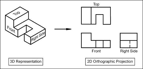
They utilize standardized line types, projection methods, and annotations to ensure consistent interpretation across different projects.
Universal Communication:
Technical drawings are designed to be understood by anyone involved in a project, regardless of their background or language.
Various Applications:
They are used in a wide range of industries, including architecture, engineering, manufacturing, and construction, to guide construction, assembly, and maintenance.
Examples of technical drawings:
-
Architectural Drawings:These include floor plans, elevations, and sections of buildings and structures.
-
Engineering Drawings:These represent mechanical parts, systems, and assemblies, providing detailed specifications for manufacturing and assembly.
-
Electrical Drawings:These depict electrical circuits and systems, guiding the installation and maintenance of electrical equipment.
-
Civil Drawings:These represent road, bridge, and tunnel designs, guiding construction and maintenance of infrastructure projects.